IBM Quantum Developer Certification Sample Test Explanation Part 2
Note: The content introduced on this page is for the previous version of the exam. For Sample Test explanations aligned with the new version of the exam, please refer to IBM Quantum Developer Certification v2.X Sample Test Explanation Part 1.
To earn the certification “IBM Certified Associate Developer - Quantum Computation using Qiskit v0.2X” provided by IBM, you need to pass the exam “Exam C1000-112: Fundamentals of Quantum Computation Using Qiskit v0.2X Developer.” In the URL below, which contains an overview of the exam, there is a link to a sample question set.
https://www.ibm.com/training/certification/ibm-certified-associate-developer-quantum-computation-using-qiskit-v02x-C0010300
I have provided explanations for questions 1 to 10 of the sample question set on the previous page. On this page, I will explain questions 11 to 20.
Amazon Braket Learning Course
I have also created a learning course on Amazon Braket, AWS’s quantum computing service.

This course is designed for those with no prior knowledge of quantum computing or AWS, and by the end, you’ll even be able to learn about quantum machine learning. Take advantage of this opportunity to build your skills in quantum technologies!
Sample Test 11:
Which two options would place a barrier across all qubits to the QuantumCircuit below?
qc = QuantumCircuit(3,3)
Options:
- A. qc.barrier(qc)
- B. qc.barrier([0,1,2])
- C. qc.barrier()
- D. qc.barrier(3)
- E. qc.barrier_all()
Answer: B, C
Explanation:
The barrier plays a role in ensuring that the gates are executed in sequence by being placed between them. In the given sample test code, three quantum and classical bits have already been defined. Let’s examine each option:
In Option A, it is not possible to place a barrier across all quantum bits, making this option incorrect.
Option B is correct as it specifies inserting a barrier between the 0th, 1st, and 2nd quantum bits.
Option C is also correct because a barrier is inserted across all quantum bits.
In Option D, only the 3rd quantum bit has a barrier, which is incorrect because only the 0th, 1st, and 2nd quantum bits have been defined. This would result in an error.
Option E would also result in an error.
Sample Test 12:
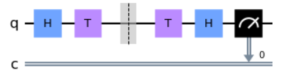
What code fragment codes the equivalent circuit if you remove the barrier in the following QuantumCircuit?
Options:
- A.
qc = QuantumCircuit(1,1)
qc.h(0)
qc.s(0)
qc.h(0)
qc.measure(0,0)
- B.
qc = QuantumCircuit(1,1)
qc.measure(0,0)
- C.
qc = QuantumCircuit(1,1)
qc.h(0)
qc.t(0)
qc.tdg(0)
qc.h(0)
qc.measure(0,0)
- D.
qc = QuantumCircuit(1,1)
qc.h(0)
qc.z(0)
qc.h(0)
qc.measure(0,0)
Answer: A
Explanation:
The given circuit includes H gates and T gates. The T gate applies a rotation of $\pi/4$ around the z-axis, and in the sample test, it is applied twice consecutively to a qubit, separated by a barrier. When the barrier is removed, the two $\pi/4$ rotations combine into a single $\pi/2$ rotation. A gate that applies a $\pi/2$ rotation around the z-axis is called an S gate. Thus, applying the T gate twice is equivalent to applying the S gate once.
After applying this circuit, the qubit will be in the following state:
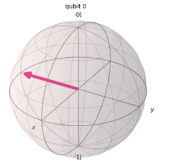
Let’s use these hints to examine each option one by one.
Option A correctly applies the S gate once instead of processing with the T gate twice. As mentioned earlier, these processes are equivalent, making this option correct.
Option B is incorrect because it does not change the qubit from its initial state $|0\rangle$.
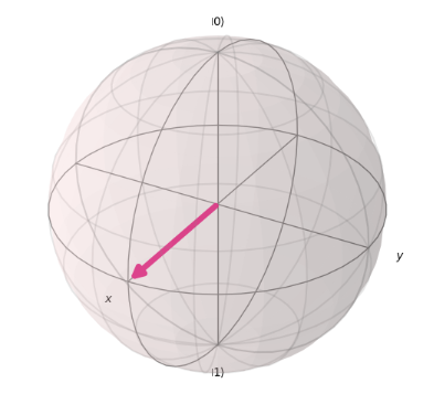
Option C introduces the TDG gate, which performs a rotation of $-\pi/2$ around the z-axis, effectively canceling the effect of the T gate. Therefore, the consecutive application of the T gate and TDG gate negates each other. Since the two remaining H gates also act consecutively, they result in no change, so the circuit maintains the initial state $|0\rangle$.
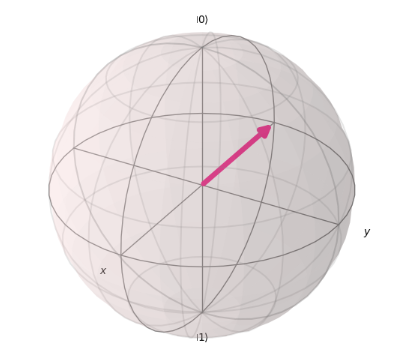
Option D applies the H gate to the state $|0\rangle$, resulting in the following state:
Sample Test 13:
Given the following code, what is the depth of the circuit?
qc = QuantumCircuit(2, 2)
qc.h(0)
qc.barrier(0)
qc.cx(0,1)
qc.barrier([0,1])
Options:
- A. 2
- B. 3
- C. 4
- D. 5
Answer: A
Explanation: In this question, you are asked about the depth of the circuit in the code provided in the sample test. The depth of a circuit generally refers to the number of gates applied to the qubit that has the most gates. In this case, barriers are not counted as part of the depth. The circuit from the sample test can be represented as follows in the diagram.
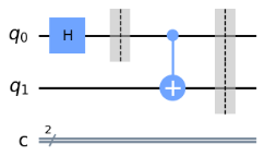
Two gates are applied to the 0th qubit, so the answer is 2.
Sample Test 14:
Which code snippet would execute a circuit given these parameters?
1) Measure the circuit 1024 times.
2) Use the QASM simulator.
3) Use a coupling map that connects three qubits linearly.
qc = QuantumCircuit(3)
# Insert code fragment here
result = job.result()
Options:
- A.
qasm_sim = Aer.get_backend('qasm_simulator')
couple_map = [[0, 1], [1, 2]]
job = execute(qc, backend=qasm_sim, shots=1024, coupling_map=couple_map)
- B.
qasm_sim = Aer.getBackend('ibmq_simulator')
couple_map = [[0, 1], [0, 2]]
job = execute(qc, loop=1024, coupling_map=couple_map)
- C.
qasm_sim = Aer.get_backend('qasm_simulator')
couple_map = [[0, 1], [1, 2]]
job = execute(qc, backend=qasm_sim, repeat=1024, coupling_map=couple_map)
- D.
qasm_sim = Aer.get_backend('qasm_simulator')
couple_map = [[0, 1], [1, 2]]
job = execute(backend=qasm_sim, qc, shot=1024, coupling_map=couple_map)
Answer: A
Explanation:
To satisfy condition 1, the circuit must be executed 1024 times. To satisfy condition 2, the QASM simulator needs to be used. For condition 3, a coupling map must be used to linearly connect the three qubits. A coupling map shows the connectivity between qubits. As confirmed with the Bell state, qubits can be made to have a relationship where the measurement result of one qubit affects the state of another. However, the connectivity between qubits varies depending on the actual quantum computer. In Qiskit’s quantum simulator, you can define your own coupling map and run simulations. For example, you can simulate the connectivity similar to that of a real quantum computer. With this in mind, let’s go through the options one by one.
In option A, Aer.get_backend('qasm_simulator') correctly defines the QASM simulator. Additionally, the coupling map defined by couple_map = [[0, 1], [1, 2]] establishes a linear connection as shown below.

Furthermore, with job = execute(qc, backend=qasm_sim, shots=1024, coupling_map=couple_map), the simulator is executed with the condition of 1024 runs, making this the correct answer.
In option B, qasm_sim = Aer.getBackend('ibmq_simulator') does not select the QASM simulator, making this the incorrect answer.
In option C, job = execute(qc, backend=qasm_sim, repeat=1024, coupling_map=couple_map) is incorrect because the argument ‘repeat’ cannot be specified.
Option D is close, but it is incorrect because the number of executions should be specified using ‘shots’ instead of ‘shot’.
Sample Test 15:
Which of these would execute a circuit on a set of qubits which are coupled in a custom way?
from qiskit import QuantumCircuit, execute, BasicAer
backend = BasicAer.get_backend('qasm_simulator')
qc = QuantumCircuit(3)
# insert code here
Options:
- A.
execute(qc, backend, shots=1024, coupling_map=[[0,1], [1,2]])
- B.
execute(qc, backend, shots=1024, custom_topology=[[0,1],[2,3]])
- C.
execute(qc, backend, shots=1024, device="qasm_simulator", mode="custom")
- D.
execute(qc, backend, mode="custom")
Answer: A
Explanation:
The coupling map that appeared in the previous sample test also comes up here. Let’s go through the options one by one.
Option A correctly specifies the coupling map using coupling_map=[[0,1], [1,2]] and executes the circuit with this custom method.
In option B, the argument custom_topology is incorrect, making it the wrong choice.
Options C and D also contain the incorrect argument mode='custom', leading to their disqualification as well.
Sample Test 16:
Which three simulators are available in BasicAer?
Options:
- A. qasm_simulator
- B. basic_qasm_simulator
- C. statevector_simulator
- D. unitary_simulator
- E. quantum_simulator
- F. quantum_circuit_simulator
Answer: A, C, D
Explanation:
In BasicAer, the available simulators are qasm_simulator, statevector_simulator, and unitary_simulator, making options A, C, and D the correct answers. Here, I will provide a brief overview of each simulator and the output results.
The qasm_simulator enables the execution of ideal and noisy multiple shots of Qiskit circuits, providing counts as output. For example, the output results can be as follows.
{'01': 504, '00': 520}
This example’s results indicate that the state $|01\rangle$ was observed 504 times, while the state $|00\rangle$ was observed 520 times.
The statevector_simulator allows for ideal single-shot execution of Qiskit circuits, providing the final state vector of the simulator after application as the result. The output of this simulator may look something like the following.
[1.+0.j 0.+0.j 0.+0.j 0.+0.j]
This result represents the state $|00\rangle$.
The unitary_simulator allows for the ideal single-shot execution of Qiskit circuits and provides the final unitary matrix of the circuit as output. The output result of this simulator is, for example, as follows.
[[1.+0.j 0.+0.j 0.+0.j 0.+0.j]
 [0.+0.j 1.+0.j 0.+0.j 0.+0.j]
 [0.+0.j 0.+0.j 1.+0.j 0.+0.j]
 [0.+0.j 0.+0.j 0.+0.j 1.+0.j]]
This example result represents the identity gate for two quantum bits.
Sample Test 17:
Which line of code would assign a statevector simulator object to the variable backend?
Options:
- A. backend = BasicAer.StatevectorSimulatorPy()
- B. backend = BasicAer.get_backend(‘statevector_simulator’)
- C. backend = BasicAer.StatevectorSimulatorPy().name()
- D. backend = BasicAer.get_back(‘statevector_simulator’)
Answer: B
Explanation:
The correct answer is B, and this format correctly assigns the state vector simulator. A, C, and D will result in errors when executed.
Sample Test 18:
Which code fragment would yield an operator that represents a single-qubit X gate?
Options:
- A.
op = Operator.Xop(0)
- B.
op = Operator([[0,1]])
- C.
qc = QuantumCircuit(1)
qc.x(0)
op = Operator(qc)
- D.
op = Operator([[1,0,0,1]])
Answer: C
Explanation:
All options attempt to generate the X gate using the Operator module. Let’s take a closer look at each one.
Option A will result in an error when executed.
B and D are attempting to define the X gate directly from the shape of the array. The X gate can be expressed mathematically as follows.
$$
X =
\begin{bmatrix}
0 & 1 \\
1 & 0
\end{bmatrix}
$$
If we were to express this using the Operator module, it would need to be written as follows.
op = Operator([[0,1],[1,0]])
Both B and D fail to define in this form, making them incorrect.
Option C correctly defines the X gate directly from the circuit, making it the right choice.
Sample Test 19:
What would be the fidelity result(s) for these two operators, which differ only by global phase?
op_a = Operator(XGate())
op_b = numpy.exp(1j * 0.5) * Operator(XGate())
Options:
- A. state_fidelity() of 1.0
- B. state_fidelity() and average_gate_fidelity() of 1.0
- C. average_gate_fidelity() and process_fidelity() of 1.0
- D. state_fidelity(), average_gate_fidelity() and process_fidelity() of 1.0
Answer: C
Explanation:
Fidelity is a measure of how similar or “close” two quantum states or quantum operators are.
It quantifies the degree of resemblance between them, often expressed as a value ranging from 0 to 1, where a fidelity of 1 indicates perfect agreement, while a fidelity of 0 indicates complete dissimilarity.
In cases like this, where only the global phase differs, the fidelity is equal to 1.
Furthermore, the fidelity of an operator can be determined using average_gate_fidelity() and process_fidelity(), making option C the correct choice.
To calculate the fidelity of quantum states, you can use the state_fidelity() function.
Sample Test 20:
Given this code fragment, which output fits most closely with the measurement probability distribution?
qc = QuantumCircuit(2, 2)
qc.x(0)
qc.measure([0,1], [0,1])
simulator = Aer.get_backend('qasm_simulator')
result = execute(qc, simulator, shots=1000).result()
counts = result.get_counts(qc)
print(counts)
Options:
- A. {‘00’: 1000}
- B. {‘01’: 1000}
- C. {‘10’: 1000}
- D. {‘11’: 1000}
Answer: B
Explanation:
First, at the point where qc = QuantumCircuit(2, 2) is defined, the quantum state is $|00\rangle$. Then, after executing qc.x(0), the 0th qubit is transformed to 1, resulting in the quantum state $|01\rangle$. Subsequently, the measurement is performed with qc.measure([0,1], [0,1]), and the measurement probability distribution is obtained from the simulator. Therefore, the result shows that $|01\rangle$ is observed 1000 times, making option B the correct answer.
Amazon Braket Learning Course
I have also created a learning course on Amazon Braket, AWS’s quantum computing service.
This course is designed for those with no prior knowledge of quantum computing or AWS, and by the end, you’ll even be able to learn about quantum machine learning. Take advantage of this opportunity to build your skills in quantum technologies!