IBM Quantum Developer Certification Sample Test Explanation Part 1
Note: The content introduced on this page is for the previous version of the exam. For Sample Test explanations aligned with the new version of the exam, please refer to IBM Quantum Developer Certification v2.X Sample Test Explanation Part 1.
In the other page, it was mentioned that, unlike classical computers, quantum computers require quantum programs to be implemented. IBM has been offering a certification related to quantum programming called ‘IBM Certified Associate Developer - Quantum Computation using Qiskit v0.2X’ since 2021.
https://www.ibm.com/training/certification/ibm-certified-associate-developer-quantum-computation-using-qiskit-v02x-C0010300
By obtaining this certification, you can demonstrate your knowledge of Qiskit and quantum programming!
To earn this certification, you need to pass the exam titled “Exam C1000-112: Fundamentals of Quantum Computation Using Qiskit v0.2X Developer,” as mentioned in the URL above. IBM also provides a sample Test related to this exam, which is available in the “Sample Test” section on the website linked above.
However, the explanations are not provided in the Sample Test page, so I will include clear explanations as much as possible. This page contains explanations for questions 1 to 10. For the explanations of questions 11 to 20, please refer to this page.
Amazon Braket Learning Course
I have also created a learning course on Amazon Braket, AWS’s quantum computing service.

This course is designed for those with no prior knowledge of quantum computing or AWS, and by the end, you’ll even be able to learn about quantum machine learning. Take advantage of this opportunity to build your skills in quantum technologies!
Sample Test 1:
Which statement will create a quantum circuit with four quantum bits and four classical bits?
Options:
- A. QuantumCircuit(4, 4)
- B. QuantumCircuit(4)
- C. QuantumCircuit(QuantumRegister(4, ‘qr0’), QuantumRegister(4, ‘cr1’))
- D. QuantumCircuit([4, 4])
Answer: A
Explanation: In the other page, I have already provided a brief explanation of qubits, but in quantum circuits, classical bits are often defined as measurement bits. In Qiskit, you can define qubits and classical bits as follows. In this example, a circuit with x qubits and y classical bits is defined in the variable qc:
qc = QuantumCircuit(x, y)
Therefore, the correct answer is A. For the other options: In B, only 4 qubits are defined, and no classical bits are included. In C, QuantumRegister is used, so classical bits are not defined. D would result in an error if executed.
Sample Test 2:
Given this code fragment, what is the probability that a measurement would result in |0> ?
qc = QuantumCircuit(1)
qc.ry(3 * math.pi/4, 0)
Options:
- A. 0.8536
- B. 0.5
- C. 0.1464
- D. 1.0
Answer: C
Explanation:
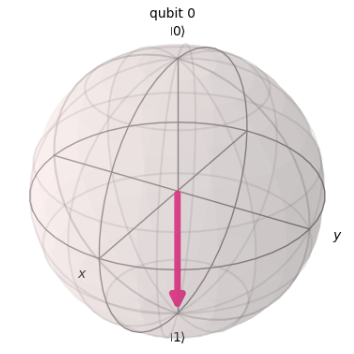
In the code from the sample test, one qubit is defined using the QuantumCircuit() function, which was introduced in sample test 1. At this point, the qubit is in the state |0>, meaning that it will always be observed as |0> upon measurement. In this state, the angle $\theta$ representing the tilt from the Z-axis is 0.
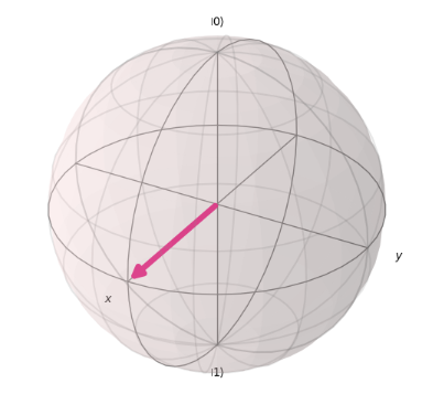
Then, at the point qc.ry(3 * math.pi/4, 0), the qubit undergoes a rotation around the Y-axis by $\theta = 3\pi/4$. After applying this operation, the qubit will be in the following state:
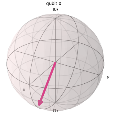
In this way, on the Bloch sphere, the vector tilts toward the direction of $|0>$ or $|1>$ depending on the value of $\theta$. When the tilt toward the $|0>$ direction is significant (i.e., $\theta < \pi/2$), the probability of measuring $|0>$ increases while the probability of measuring $|1>$ decreases. Conversely, when the tilt toward the $|1>$ direction is significant (i.e., $\pi/2 < \theta$), the probability of measuring $|1>$ increases while the probability of measuring $|0>$ decreases. In this case, as illustrated in the figure, the tilt toward the $|1>$ direction is significant, resulting in a decreased probability of measuring $|0>$. However, since the state does not perfectly align with $|1>$, the probability of measuring $|0>$ is not zero. Therefore, the correct answer is C.
Certainly, you can also represent qc.ry(3*math.pi/4, 0) as a matrix, manually calculate the value of RY|0>, and determine the probability. The representation of RY|0> using matrices and vectors is as follows, which leads to the same conclusion as before.
$$ R_{y(3\pi/4)} |0\rangle = \begin{bmatrix} \cos\frac{3\pi}{8} & -\sin\frac{3\pi}{8} \\ \sin\frac{3\pi}{8} & \cos\frac{3\pi}{8} \end{bmatrix} \begin{bmatrix} 1 \\ 0 \end{bmatrix} = \cos\frac{3\pi}{8} |0\rangle + \sin\frac{3\pi}{8} |1\rangle $$
$$
\left|\cos\frac{3\pi}{8}\right|^2 \approx 0.1464
$$
where
$$
R_{y(\theta)} =
\begin{bmatrix}
\cos\frac{\theta}{2} & -\sin\frac{\theta}{2} \\
\sin\frac{\theta}{2} & \cos\frac{\theta}{2}
\end{bmatrix}
$$
Sample Test 3:
Assuming the fragment below, which three code fragments would produce the circuit illustrated?
inp_reg = QuantumRegister(2, name='inp')
ancilla = QuantumRegister(1, name='anc')
qc = QuantumCircuit(inp_reg, ancilla)
# Insert code here
Options:
- A.
qc.h(inp_reg)
qc.x(ancilla)
qc.draw()
- B.
qc.h(inp_reg[0:2])
qc.x(ancilla[0])
qc.draw()
- C.
qc.h(inp_reg[0:1])
qc.x(ancilla[0])
qc.draw()
- D.
qc.h(inp_reg[0])
qc.h(inp_reg[1])
qc.x(ancilla[0])
qc.draw()
- E.
qc.h(inp_reg[1])
qc.h(inp_reg[2])
qc.x(ancilla[1])
qc.draw()
- F.
qc.h(inp_reg)
qc.h(inp_reg)
qc.x(ancilla)
qc.draw()
Answer: A,B,D
Explanation:
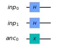
Let’s start by examining the code from the Sample test. In this example, a quantum circuit is created by defining 2 qubits in the variable inp_reg under the name inp, and 1 qubit in ancilla with the name anc. From the diagram, we can observe that an H gate is applied to the 0th and 1st qubits of inp_reg, while an X gate is applied to the 0th qubit of ancilla. The correct solution should replicate this behavior. Let’s break it down step by step.
Option A applies an H gate to all of inp_reg and an X gate to all of ancilla, making it correct.
Option B applies an H gate to the 0th and 1st qubits of inp_reg and an X gate to the 0th qubit of ancilla, so it is also correct.
Option C applies an H gate to the 0th qubit of inp_reg and an X gate to the 0th qubit of ancilla, but fails to apply an H gate to the 1st qubit of inp_reg, making it incorrect.
Option D applies an H gate to the 0th and 1st qubits of inp_reg and an X gate to the 0th qubit of ancilla, making it correct.
Option E applies an H gate to the 1st and 2nd qubits of inp_reg and an X gate to the 1st qubit of ancilla, making it incorrect.
Option F applies an H gate twice to all of inp_reg and an X gate to all of ancilla, making it incorrect because there is no need to apply the H gate twice.
Sampe Test 4:
Given an empty QuantumCircuit object, qc, with three qubits and three classical bits, which one of these code fragments would create this circuit?
Options:
- A. qc.measure([0,1,2], [0,1,2])
- B. qc.measure([0,0], [1,1], [2,2])
- C. qc.measure_all()
- D. qc.measure(0,1,2)
Answer: A
Explanation:
In the code from the sample test, three qubits are measured using three classical bits. Let’s go through it step by step.
Option A correctly measures the 0th, 1st, and 2nd qubits using the 0th, 1st, and 2nd classical bits, making it the correct answer.
Option B has an incorrect format and will result in an error when executed.
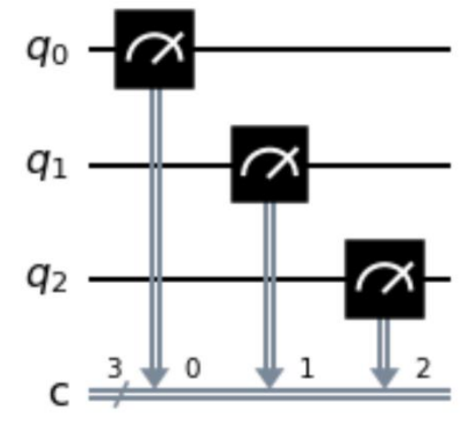
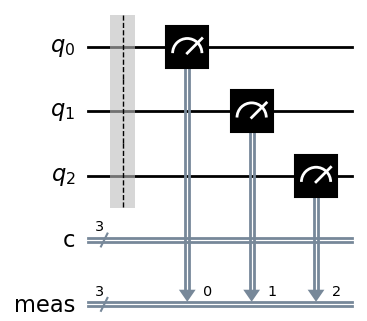
Option C uses qc.measure_all(), and while this is close, it does not use the pre-defined classical bits. Instead, it generates a circuit like the one shown below, which makes it incorrect.
Sample Test 5:
Which code fragment will produce a maximally entangled, or Bell, state?
Options:
- A.
bell = QuantumCircuit(2)
bell.h(0)
bell.x(1)
bell.cx(0, 1)
- B.
bell = QuantumCircuit(2)
bell.cx(0, 1)
bell.h(0)
bell.x(1)
- C.
bell = QuantumCircuit(2)
bell.h(0)
bell.x(1)
bell.cz(0, 1)
- D.
bell = QuantumCircuit(2)
bell.h(0)
bell.h(0)
Answer: A
Explanation: A Bell state refers to a state where measuring the state of one qubit determines the state of the other, as shown below.
$$
\begin{align*}
|\Phi^+\rangle &= \frac{1}{\sqrt{2}} (|00\rangle + |11\rangle), \\
|\Phi^-\rangle &= \frac{1}{\sqrt{2}} (|00\rangle - |11\rangle), \\
|\Psi^+\rangle &= \frac{1}{\sqrt{2}} (|01\rangle + |10\rangle), \\
|\Psi^-\rangle &= \frac{1}{\sqrt{2}} (|01\rangle - |10\rangle).
\end{align*}
$$
For example, in the states $|\Psi^+\rangle$ and $|\Psi^-\rangle$ shown above, if the 0th qubit is measured as 1, it immediately determines that the 1st qubit will be 0.
In this sample test, to create a Bell state, it is necessary to use a CX gate. The CX gate operates on two qubits: a control qubit and a target qubit. If the control qubit is in the state 1, an X gate is applied to the target qubit; if the control qubit is in the state 0, nothing happens.
Therefore, since options C and D do not include a CX gate, we can already determine that they are incorrect.
To create a Bell state, the control qubit must be in a state such as $|+\rangle = \frac{1}{\sqrt{2}} (|0\rangle + |1\rangle)$ or $|-\rangle = \frac{1}{\sqrt{2}} (|0\rangle - |1\rangle)$, where the probability of measuring 0 or 1 is 1/2. The target qubit, on the other hand, must be in a well-defined state of either $|0\rangle$ or $|1\rangle$.
In option A, the 0th qubit is transformed into the $|+\rangle$ state by the H gate, while the 1st qubit is in the definite state of $|1\rangle$. Since the CX gate is applied afterward, this option is correct.
In option B, both the 0th and 1st qubits are in the $|0\rangle$ state, and though the CX gate is applied, this makes the option incorrect.
Sample Test 6:
Given this code, which two inserted code fragments result in the state vector represented by this Bloch sphere?
qc = QuantumCircuit(1,1)
# Insert code fragment here
simulator = Aer.get_backend('statevector_simulator')
job = execute(qc, simulator)
result = job.result()
outputstate = result.get_statevector(qc)
plot_bloch_multivector(outputstate)
Options:
- A. qc.h(0)
- B. qc.rx(math.pi / 2, 0)
- C. qc.ry(math.pi / 2, 0)
- D. qc.rx(math.pi / 2, 0)
qc.rz(-math.pi / 2, 0) - E. qc.ry(math.pi, 0)
Answer: A, C
Explanation:
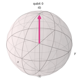
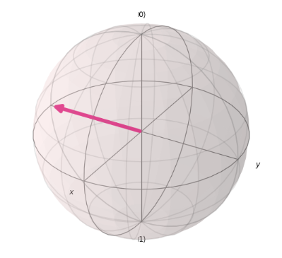
Looking at the code, a qubit is defined using QuantumCircuit(1,1), followed by a section where additional code is added. The qubit, immediately after being defined by QuantumCircuit(), is in the $|0\rangle$ state. The correct code will update this to the state $|+\rangle = \frac{1}{\sqrt{2}} (|0\rangle + |1\rangle)$ as shown in the diagram. Let’s go through it step by step.
In A, an H gate is applied, which transforms the $|0\rangle$ qubit into the $|+\rangle$ state as shown in the diagram. Therefore, A is correct.
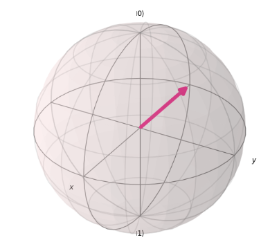
In B, a rotation of $\pi/2$ around the X-axis is applied, changing the $|0\rangle$ qubit to the following state. As a result, B is incorrect.
In D, the operation qc.rx(math.pi / 2, 0) applies a rotation of $\pi/2$ around the X-axis, changing the qubit to the following state.
qc.rz(-math.pi / 2, 0) applies a rotation of $-\pi/2$ around the Z-axis, resulting in the final state as shown below. Therefore, D is incorrect.
Sample Test 7:
S-gate is a Qiskit phase gate with what value of the phase parameter?
Options:
-
A. $\pi/4$
-
B. $\pi/2$
-
C. $\pi/8$
-
D. $\pi$
Answer: B
Explanation: Gates that apply rotations around the Z-axis include the T, S, and Z gates, which rotate the state by phases of $\pi/4$, $\pi/2$, and $\pi$ respectively. Therefore, the correct answer is B.
Sample Test 8:
Which two code fragments, when inserted into the code below, will produce the statevector shown in the output?
from qiskit import QuantumCircuit, Aer, execute
from math import sqrt
qc = QuantumCircuit(2)
# Insert fragment here
simulator = Aer.get_backend('statevector_simulator')
result = execute(qc, simulator).result()
statevector = result.get_statevector()
print(statevector)
Output:
[0.707+0.j 0.+0.j 0.+0.j 0.707+0.j]
Options:
- A.
v = [1/sqrt(2), 0, 0, 1/sqrt(2)]
qc.initialize(v,[0,1])
- B.
qc.h(0)
qc.cx(0,1)
- C.
v1, v2 = [1,0], [0,1]
qc.initialize(v1,0)
qc.initialize(v2,1)
- D.
qc.cx(0,1)
qc.measure_all()
- E.
qc.h(0)
qc.h(1)
qc.measure_all()
Answer: A, B
Explanation:
Since there are 2 qubits, the state vector in the output will have four values, corresponding to the coefficients of $|00\rangle$, $|01\rangle$, $|10\rangle$, and $|11\rangle$, respectively. In this case, the output shows that only $|00\rangle$ and $|11\rangle$ have a coefficient of 0.707+0.j, meaning that the state corresponds to $|\Phi^+\rangle = \frac{1}{\sqrt{2}} (|00\rangle + |11\rangle)$. Now, let’s determine which code can transform the initial $|00\rangle$ state into this one. We’ll review each option step by step.
In option A, qc.initialize(v, [0,1]) is used to initialize the 0th and 1st qubits, and the vector v = [1/sqrt(2), 0, 0, 1/sqrt(2)] matches the state vector in the output. Therefore, A is the correct answer.
In option B, the 0th qubit is transformed into the state $|+\rangle = \frac{1}{\sqrt{2}} (|0\rangle + |1\rangle)$ by applying the H gate, and then a CX gate is applied with the 0th qubit as the control and the 1st qubit as the target. If the 0th qubit is observed as $|0\rangle$, the CX gate does nothing to the 1st qubit, resulting in the state $|00\rangle$. If the 0th qubit is observed as $|1\rangle$, the CX gate applies an X gate to the 1st qubit, resulting in the state $|11\rangle$. Therefore, the quantum state becomes $\frac{1}{\sqrt{2}} (|00\rangle + |11\rangle)$, making this option also correct.
In option C, the 0th qubit is initialized with qc.initialize(v1, 0), resulting in the qubit being in the state $|0\rangle$, and the 1st qubit is initialized with qc.initialize(v2, 1), resulting in the qubit being in the state $|1\rangle$. The final state is $|10\rangle$, making this incorrect.
In option D, a CX gate is applied to the initial state $|00\rangle$, but since the 0th qubit is observed as 0, the CX gate does nothing, leaving the state as $|00\rangle$. Therefore, this option is also incorrect.
In option E, applying H gates to both the 0th and 1st qubits results in both qubits being in the state $|+\rangle$. Combining both qubits leads to the two-qubit state $\frac{1}{2} (|00\rangle + |01\rangle + |10\rangle + |11\rangle)$. Since this state is different from $|\Phi^+\rangle$, this option is also incorrect.
Sample Test 9:
Which code fragment will produce a multi-qubit gate other than a CNOT ?
Options:
-
A. qc.cx(0,1)
-
B. qc.cnot(0,1)
-
C. qc.mct([0],1)
-
D. qc.cz(0,1)
Answer: D
Explanation:
Let’s examine each option one by one.
Option A defines a CX gate, making it incorrect.
Option B uses qc.cnot(0,1), which is equivalent to a CX gate, so it is also incorrect.
Option C utilizes qc.mct([0], 1), which defines a multi-controlled Toffoli gate. This gate can specify multiple bits as control bits and applies an X gate to the target bit when all control bits are in the state $|1\rangle$. However, since only the 0th qubit is specified as the control bit in this case, it effectively results in a gate similar to a CX gate. Therefore, this option is also incorrect.
Option D applies the CZ gate, which applies a Z gate to the target bit when the control bit is $|1\rangle$ and does nothing when the control bit is $|0\rangle$. Since this is a different multi-qubit gate compared to the CX gate, this option is correct.
Sample Test 10:
Which code fragment will produce a multi-qubit gate other than a Toffoli?
Options:
- A.
qc.ccx(0,1,2)
- B.
qc.mct([0,1], 2)
- C.
from qiskit.circuit.library import CXGate
ccx = CXGate().control()
qc.append(ccx, [0,1,2])
- D.
qc.cry(0,1,2)
Answer: D
Explanation:
The multi-controlled Toffoli gate, as mentioned in sample test 9, allows you to specify multiple bits as control bits and applies an X gate to the target bit when all control bits are in the state $|1\rangle$. Let’s go through the options one by one.
Option A is called the CCX gate, which also applies an X gate to the target bit when all control bits are in the state $|1\rangle$. Therefore, it is similar to the Toffoli gate and is incorrect. In the expression qc.ccx(0, 1, 2), the 0th and 1st qubits are treated as control bits, while the 2nd qubit serves as the target bit.
Option B is a multi-controlled Toffoli gate, which is incorrect. In the expression qc.mct([0, 1], 2), the 0th and 1st qubits are treated as control bits, while the 2nd qubit serves as the target bit.
Option C imports the CX gate using from qiskit.circuit.library import CXGate and utilizes the .control() method, such as ccx = CXGate().control(), to add additional control bits to create a CCX gate. Therefore, this option is also incorrect.
Option D is known as the controlled rotation Y gate, which applies a rotation about the Y-axis when the control bit is in the state $|1\rangle$. This is a different multi-qubit gate and is therefore correct. In the expression qc.cry(0, 1, 2), the 1st qubit is treated as the control bit, while the 2nd qubit is the target bit, and the rotation angle is 0.
Amazon Braket Learning Course
I have also created a learning course on Amazon Braket, AWS’s quantum computing service.
This course is designed for those with no prior knowledge of quantum computing or AWS, and by the end, you’ll even be able to learn about quantum machine learning. Take advantage of this opportunity to build your skills in quantum technologies!